Fortigate guide for Begineer - 7


I've been written Basic Fortigate Unit Configuration up to part 1 to 6.
Now...I am going to write Advance Configuration Steps.

Most of the Company have two Internet Line for Primary and Backup.

I'd like to write how to setup two Internet line on one Fortigate unit.
Let's assume Primary Internet Line use Static IP and Backup Internet Line DHCP IP.
Here, I will use some IP address to configure Fortigate. You need to use real IP address of yours instead.

Firstly, I'm gonna setup Primary Intenet line.
- Connect the Line from Primary ISP to the WAN1 Port of Fortigate Unit.
- Log in to Fortigate by using Web-based Manager.
- Go to System>Network>Interface and Select WAN1 Interface. Then Edit as following picture


- Select Internal Interface and Edit as following,


- Go to Router>Static>Static Route and Select Create New. Add Default Route then.


- Go to System>Network>DNS. Add Primary, Secondary DNS serers address.
- Go to Policy>Poliicy>Policy. Select Create New and define the Security Policy as following picture to get Internet Access for Private/Internal Network through from WAN1 interface.
  Some Fortigate Model configured this as Default Policy.
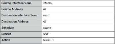


- Select Enable NAT and Use Destination Interface Address.
- Select OK to save Security Poliicy.


Primary Internet Line Setup Task done. Now I'm gonna setup Backup Internet line.
- Connect Backup Internet Line to WAN2 port of Fortigate.
- Log in to Fortigate by using Web-Based Manager.
- Go to System>Network>Interface and Edit WAN2 Interface.
- Change Addressing Mode to DHCP. Select Retrieve Default Gateway from server. Uncheck the Override internal DNS checkbox.
- Select OK to save.
(Do not forget to select Retrieve Default Gateway from server to add Default Route into Routing Table)
- Go to Policy>Policy>Policy. Select Create New and Define Security Policy as following picture. To get Internet access from Private/Internal Network through from WAN2 interface.
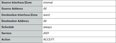


- Select Enable NAT and Use Destination Interface Address.
- Select OK to save Security Policy.
Backup line setup done.

Now I'm going to set the default route to WAN1 to be the primary default route and add a ping server for WAN1 and WAN2
The Ping Servers Verifiy the ability of the WAN1 and WAN2 interfaces to connect to the Internet.


- Go to Router>Static>Static Route. Edit the WAN1 Default Route. Select Advance and set Distance to value to 10. (By Default it is 10).
- Go to System>Network>Interface. Edit the WAN2 Interface. Set Distance to value to 20. ( The value of Distance to can set any number higher than 10)
- To confirm which default route is now actually being used by the Fortigate unit, go to Router>Monitor>Routing Monitor to view the current Fortigate routing table.


- Go to Router>Static>Settings. Select Create New and Add Ping Server for WAN1 as following picture,


- Add Ping Server for WAN2 as following picture.


OK... Now settiing up two Internet line in one Fortigate unit is done.


May you all be happy.
(Be knowledgeable, pass it on then)


Comments

Popular posts from this blog

Fortigate guide for Begineer - 6

I would like to explaine how to troubleshoot the Fortigate Unit configured by Transparent Mode in step by step this time. Let's assume, you have one Fortigate Unit that configured as Transparent Mode. But devices from Internal/Private Network unable to access Internet/Public Network through your Fortigate Unit. OK. Let's troubleshoot with following steps, 1) Check the physical network connections between the network and the FortiGate unit, and between the FortiGate unit and the Internet. 2) Check the router and ISP-supplied equipment to make sure it is operating correctly. 3) Verify that you can connect to the internal interface by connecting to the management IP address of the FortiGate unit from the Internal network. From the internal network, attempt to ping the management IP address. If you cannot connect to the internal interface, verify the IP configuration of the PC and make sure the cables are connected and all switches and other devices on the network are powered on a

Solving the "A general system error occured:Invalid fault" error in vSphere 4

Below error was come out when you try to migrate VM to other host for some reason. Below error was come out when you try to edit VM setting. Below error was come out when you power on the VM. How to solve those error? Here is how I resolve the error! Login to the Host that errored VM exist by using Terminal or Direct Console. Enter below command and press enter. services.sh restart Wait until all VMware Services are restarted. After that try to Power On/Edit Settings or Migrate the errored VM and you will see all you can do without any error pop-up. This kind of errors can occur if you shutdown/restart VM unproperly or shutdown/restart the Host unproperly that VM exist. You can check log file deeply if you willing to know precisely on this. May you all be happy. (Be knowledgeable, pass it on then)

Link Aggregating with Synology NAS and Cisco Switch

I’d like to share how to setup Link Aggregating between Synology NAS and Cisco Switch. I’ve got one Synology NAS with 4 Network Ports and I’m going to use 2 of them. Both Network Port to be as one Logical Link, Fault Tolerance and Load Balancing. To do that, I need to configure Link Aggregating on Synology NAS and EtherChannel with LACP on Cisco Switch. Below is brief steps to do to meet with my requirements. - Get connected Synology NAS and Cisco Switch as shown in picture. - Bonding two Network Ports of Synology NAS and assign IP Address - Configure EtherChannel with LACP in Cisco Switch and add two physical ports as Member. OK. Let’s begin from Synology NAS. - Login to the Synology and go to Control Panel>Network>Create>Create Bond - Select IEEE 802.3ad to get Fault Tolerance and Load Balancing Featureyou’re your switch not support 802.3ad you can only select Fault Tolerance only feature). After that click “Next”. - Choose the network port f